��������
The structure of the injection mold
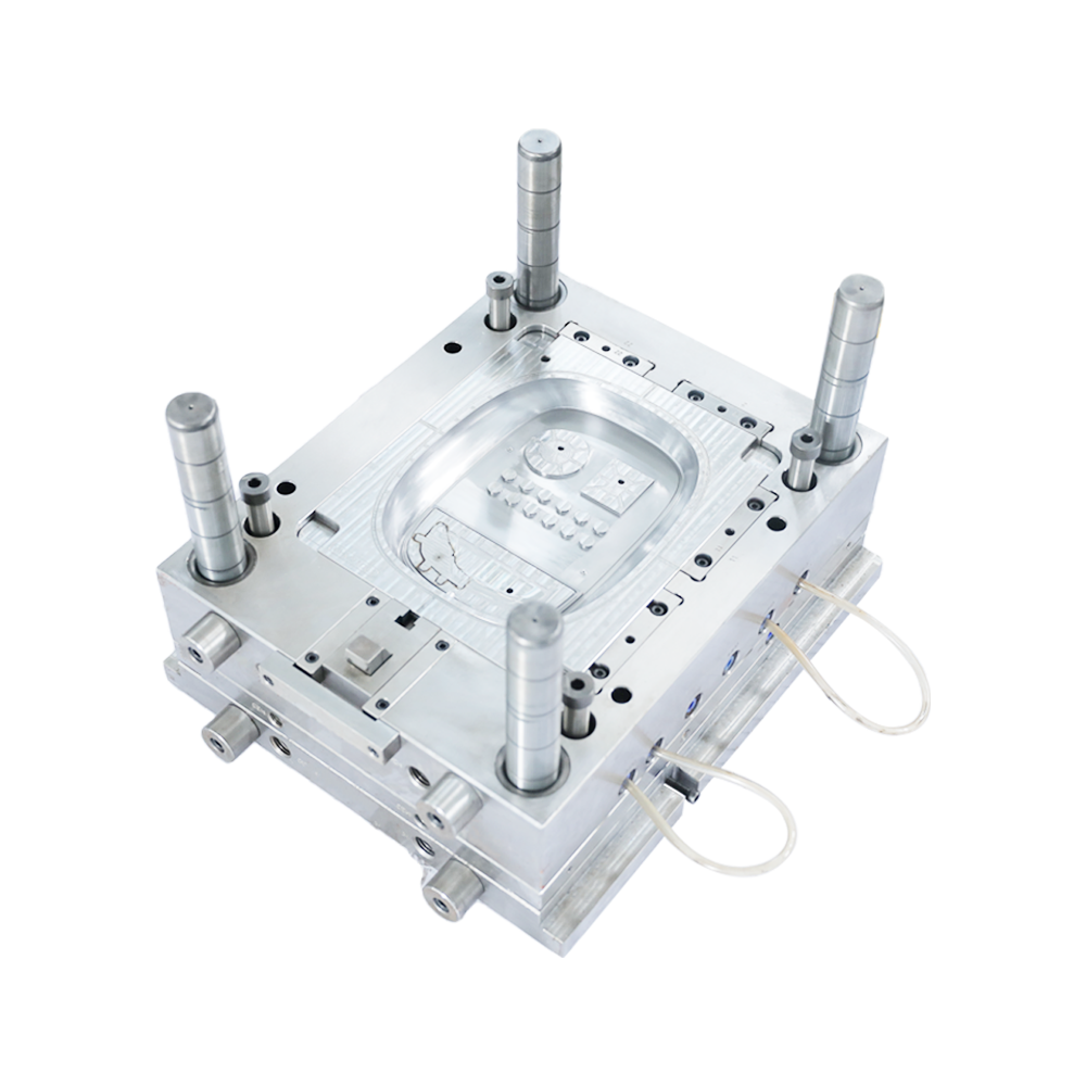
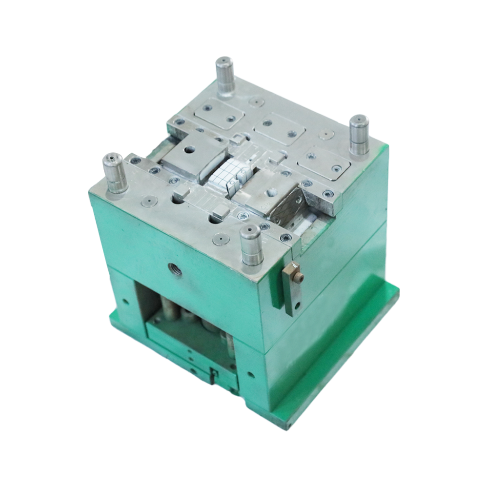
Although the structure of the mold may vary due to the variety and performance of plastics, the shape and structure of plastic products, and the type of injection machine, the basic structure is the same. The mold is mainly composed of pouring system, temperature regulation system, forming parts and structural parts. Among them, the gating system and the molding parts are the parts that are in direct contact with the plastic, and change with the plastic and the product. They are the most complex and most variable parts in the mold, and require the highest processing finish and precision.
The injection mold consists of a movable mold and a fixed mold. The movable mold is installed on the moving template of the injection molding machine, and the fixed mold is installed on the fixed template of the injection molding machine. During injection molding, the movable mold and the fixed mold are closed to form a gating system and a cavity. When the mold is opened, the movable mold and the fixed mold are separated to take out the plastic product. In order to reduce the heavy workload of mold design and manufacturing, most of the injection molds use standard mold bases.
Gating system
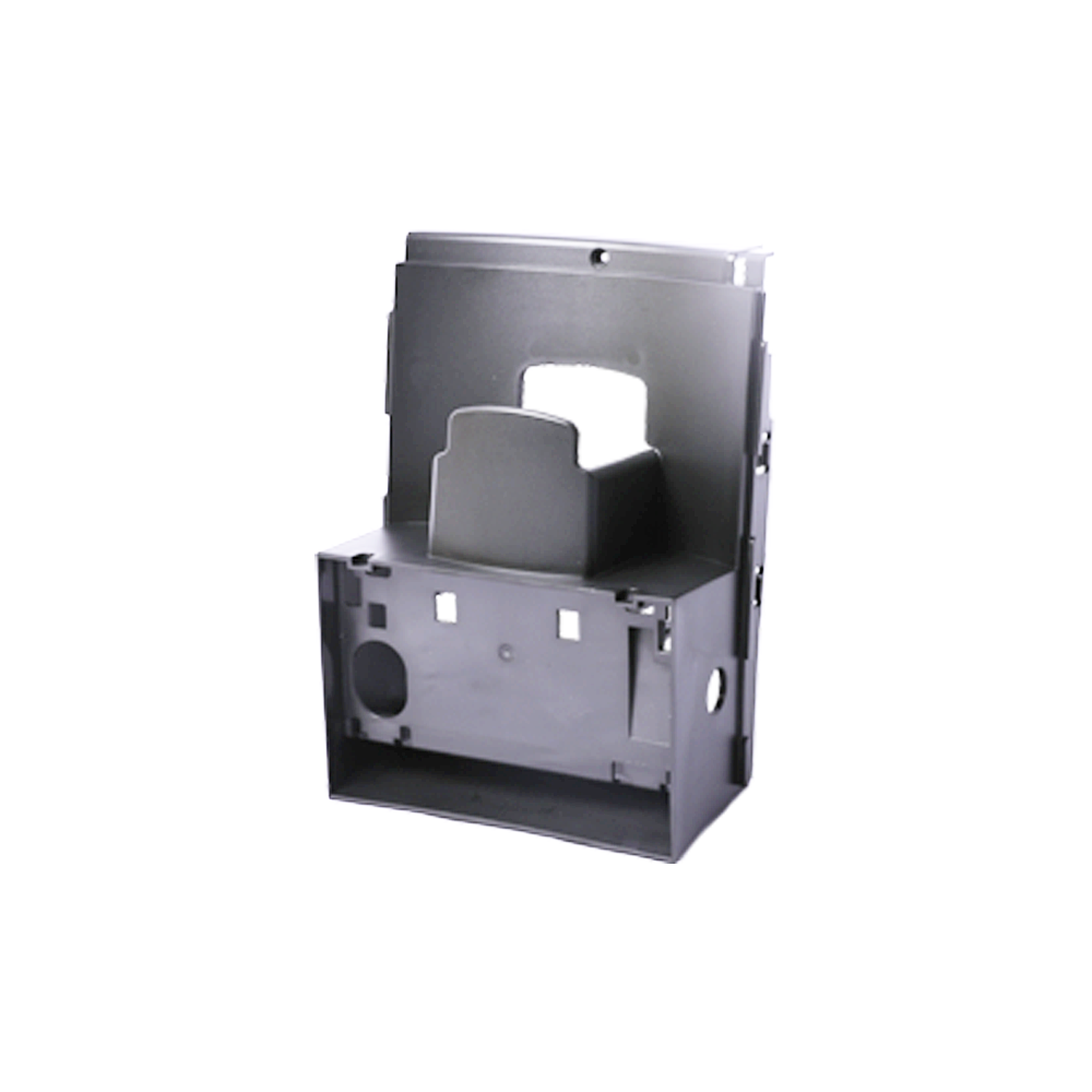
The gating system refers to the part of Charger top cover mold Plant the runner before the plastic enters the cavity from the nozzle, including the main runner, the cold material hole, the runner and the gate. The gating system is also called the runner system. A set of feeding channels to the cavity, usually composed of a main channel, a branch channel, a gate and a cold material cavity. It is directly related to the molding quality and production efficiency of plastic products
Mainstream
It is a passage in the mold that connects the injection nozzle of the injection molding machine to the runner or cavity. The top of the sprue is concave for engagement with the nozzle. The inlet diameter of the main channel should be slightly larger than the diameter of the nozzle (0.8mm) to avoid overflow and prevent the two from being blocked due to inaccurate connection. The diameter of the inlet depends on the size of the product, generally 4-8mm. The diameter of the sprue should be expanded inward at an angle of 3° to 5° to facilitate the release of the runner debris.
cold slug
It is a cavity at the end of the main channel to capture the cold material generated between two injections at the end of the nozzle, thereby preventing the blockage of the runner or gate. If the cold material is mixed into the cavity, internal stress is easily generated in the manufactured product.
The diameter of the cold material hole is about 8-10mm and the depth is 6mm. In order to facilitate demoulding, the bottom is often borne by the demoulding rod. The top of the demoulding rod should be designed as a zigzag hook or a sunken groove, so that the sprue can be pulled out smoothly when demoulding.
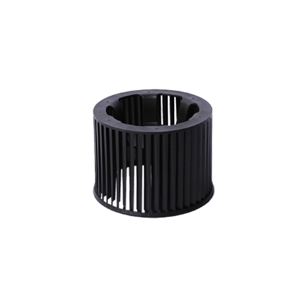
shunt
It is the channel connecting the main channel and each cavity in the multi-slot mold. In order to make the melt fill each cavity at the same speed, the arrangement of the runners on the mold should be symmetrical and equidistant. The shape and size of the runner section have an impact on the flow of the plastic melt, the demolding of the product and the ease of mold manufacturing.
If the flow of the same amount of material is considered, the flow channel resistance with a circular cross-section is the smallest. However, because the specific surface of the cylindrical runner is small, it is not good for the cooling of the runner excess, and the runner must be opened on the two halves of the mold, which is labor-intensive and difficult to align.
Therefore, trapezoidal or semi-circular cross-section runners are often used, and are opened on half of the mold with ejector bars. The runner surface must be polished to reduce flow resistance and provide faster filling speed. The size of the runner depends on the type of plastic, the size and thickness of the product. For most thermoplastics, the cross-sectional width of the runner is not more than 8m, the extra large can reach 10-12m, and the extra small is 2-3m. Under the premise of meeting the needs, the cross-sectional area should be reduced as much as possible to increase the shunting duct debris and prolong the cooling time.
gate
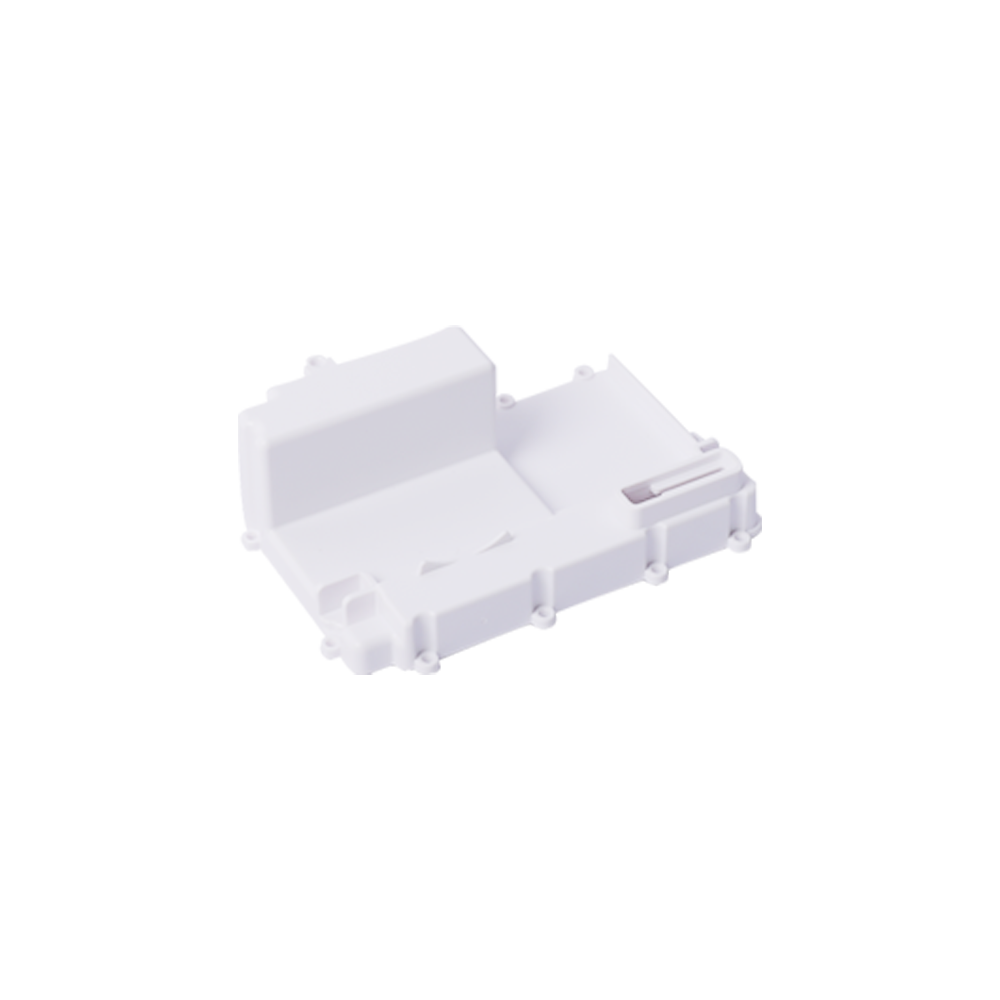
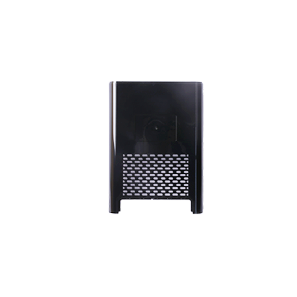
It is the channel that connects the main channel (or shunt channel) and the cavity. The cross-sectional area of Breath collector upper cover mold Plant the channel can be equal to the main channel (or branch channel), but it is usually reduced. Therefore, it is the part with the smallest cross-sectional area in the entire runner system. The shape and size of the gate have a great influence on the quality of the product.